
BIRDS OF THE DAMNED
It seems "Birds-of-the-Damned" will be an annual project for me. Last year I hand-built a prototype for this Halloween decoration. This year I finalized the schematic and firmware and ran two spins using OSH Park's excellent prototyping service.


The first spin of the board proved out the schematic and this second explored how small I could get the two-layer board.
details
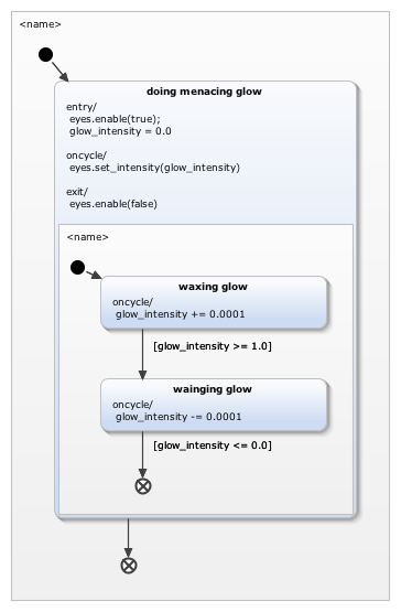
One note on the statemachine here: the main loop of the firmware runs the machine waiting for it to become finalized. When this happens the core enters a deep sleep mode that causes the peripherals to lose all state. The only thing still operational in this mode is the "wake on interrupt" pin connected to the MAX440009 light sensor. When a daylight threshold has been crossed this interrupt fires and wakes up the core which immediately resets itself to rebuild state.

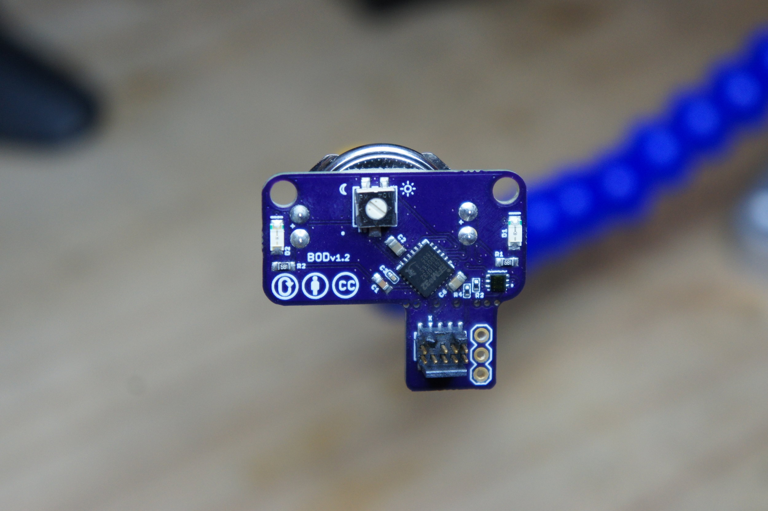
Front of PCB. D1 and D2 are where the LEDs go.
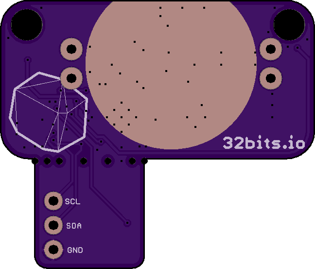
Back of PCB with exposed ground for the CR2032's cathode.